| Oracle® Communications Data Model Installation Guide Release 11.3.1 Part Number E28441-04 |
|
|
PDF · Mobi · ePub |
| Oracle® Communications Data Model Installation Guide Release 11.3.1 Part Number E28441-04 |
|
|
PDF · Mobi · ePub |
This appendix shows how to install and set up the following:
Oracle Communications Network Charging and Control Adapter for Oracle Communications Data Model (NCC Adapter)
Oracle Data Integrator components to create an operational E-LT environment
Oracle GoldenGate Extract and Replicat processes
This appendix includes the following sections:
Oracle Communications Data Model NCC Adapter Installation Overview
Setting Up Staging Schema for Oracle Communications Data Model NCC Adapter
Configuring Oracle Data Integrator for Oracle Communications Data Model NCC Adapter
Setting Up Oracle GoldenGate for Oracle Communications Data Model NCC Adapter
Note:
The steps in this section can take a significant amount of time to complete.The NCC Adapter that is installed with the Application Adapters type installation feeds pre-paid billing data from the Oracle Communications Network Charging and Control application to the Oracle Communications Data Model. The NCC Adapter includes an option to feed data in real-time using Oracle GoldenGate to the Oracle Communications Data Model staging layer, or to extract, load and transform the data in batch mode using Oracle Data Integrator.
The following are prerequisites for installing the Oracle Communications Network Charging and Control Adapter for Oracle Communications Data Model (NCC Adapter):
Before following the steps in this appendix you need to perform an Application Adapters installation, as described in "Types of Installations Provided for Oracle Communications Data Model" and in "Installer Execution".
Before following the steps in this appendix, you need to install Oracle Data Integrator software. For more information, see "Confirming that Oracle Data Integrator Enterprise Edition is Installed".
Before following the steps in this appendix, if select to use real-time feeds with Oracle GoldenGate, then you need to download the Goldengate software according to the NCC Adapter source database version and Oracle Communications Data Model target database version before starting this adapter installation. For more information, see "Installing Oracle GoldenGate".
The installation and set up steps assume the following recommended Oracle Data Integrator configuration:
The Data Warehouse database schema is hosted on the same database instance as the ODI Repository.
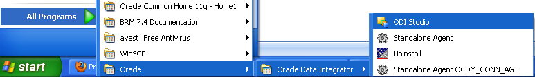
To verify your Oracle Data Integrator Enterprise Edition installation, launch ODI Studio:
Select Start Menu > All Programs > Oracle > Oracle Data Integrator > ODI Studio.
In Designer Navigator, click Connect To Repository...
If Oracle Data Integrator Enterprise Edition is not installed, see "Oracle Data Integrator Enterprise Edition".
If you install the Oracle Communications Network Charging and Control Adapter for Oracle Communications Data Model (NCC Adapter), using, installing, and configuring Oracle GoldenGate is optional depending on whether you want to use Real-time staging with the NCC Adapter.
If Oracle GoldenGate is not installed, see "Oracle GoldenGate".
This appendix includes instructions for setting up the staging database for data loading, transformation, and validation of source data. To begin working you need to set up ODI Master Repository and Work Repository and use Oracle Data Integrator (ODI) and optionally if you are using Oracle GoldenGate, you need to install and configure Oracle GoldenGate to perform real-time ETL.
Execute the following scripts in the Oracle Communications Data Model schema (OCDM_SYS) to insert unknown (-1) records into all reference tables to maintain referential integrity between Oracle Communications Data Model tables with NCC source data.
Scripts Location:
"$NCC_OCDM_HOME/utl/disable_constraint.sql”
"$NCC_OCDM_HOME/utl/enable_constraint.sql”
"$NCC_OCDM_HOME/utl/insert_dummy_reference.sql”
"$NCC_OCDM_HOME/utl/disable_constraint_final.sql”
Connect to the OCDM_SYS schema from sqlplus, from "$NCC_OCDM_HOME/utl” directory and execute the following scripts as follows:
SQL> @./disable_constraint.sql
SQL> @./enable_constraint.sql
SQL> @./insert_dummy_reference.sql

SQL> exec disb_cons;
SQL> exec insert_ref;
SQL> exec enab_cons;
SQL> @./disable_constraint_final.sql
The procedures do the following:
disb_cons: disable all the constraints in Oracle Communications Data Model.
insert_ref: insert one record with value -1 in all reference tables.
enab_cons: enable all the disabled constraints.
The scripts in "disable_constraint_final.sql" disable some specific Oracle Communications Data Model FK constraints to insert NCC source data.
The following describes the NCC Adapter staging schema:
Staging Schema Creation (for example: ncc_stg)
Create staging schema (ncc_stg) by executing the following create_ncc_stg.sql file from sqlplus by connecting sys/system users:
Script Location: "$NCC_OCDM_HOME/staging_install_ddl/create_ncc_stg.sql"
SQL> @./create_ncc_stg.sql
Creating Relational Schema and Granting required privilages
Enter value for user_name:ncc_stg
Enter value for password:ncc_stg
Connecting Target Schema (for example:OCDM_SYS)
Enter value for user_name: ocdm_sys
Enter value for password: passwd
Staging Schema (ncc_stg) Objects
The create_ncc_stg.sql file executes the following files and creates the following objects in the ncc_stg schema and target ocdm_sys schema:
Staging Schema (ncc_stg) Objects:
Normal Staging Tables (Table name is same as source table name)
Previous Day Tables (**_LD)
Delta Tables (**_DELTA)
Delta History Tables (**_DELTA_H)
Event Detail Record (EDR) Functions
Event Detail Record (EDR) Types
Event Detail Record (EDR) Views
Staging load Procedures (post_staging_load, pre_ocdm_load & pre_staging_load)

Target Schema (ocdm_sys) Objects:

Update Churn Date Procedure (update_churn_date)
Look Up Tables Load Procedure (Look_Up_load_One_Time)
Reference Tables Update Procedures
(update_acct,
update_cnrt,
update_cust,
update_prod,
update_prpd_vchr_instnc &
update_sbrp)
"
Staging Schema (ncc_stg) Files
Staging Schema (ncc_stg) Objects Creation Files:
Scripts Location:
"$NCC_OCDM_HOME/staging_install_ddl/ddl_rqd_tables_stg_delta.sql"
"$NCC_OCDM_HOME/staging_install_ddl/ddl_rqd_tables_stg_delta_h.sql"
"$NCC_OCDM_HOME/staging_install_ddl/ddl_rqd_tables_stg_ld.sql"
"$NCC_OCDM_HOME/staging_install_ddl/ddl_rqd_tables_stg_normal.sql"
"$NCC_OCDM_HOME/staging_install_ddl/edr_package.sql"
"$NCC_OCDM_HOME/staging_install_ddl/edr_types.sql"
"$NCC_OCDM_HOME/staging_install_ddl/edr_views.sql"
"$NCC_OCDM_HOME/staging_install_ddl/procedure_rqd_stg.sql"
"$NCC_OCDM_HOME/staging_install_ddl/procedure_rqd_trg.sql"
"$NCC_OCDM_HOME/staging_install_ddl/ddl_rqd_tables_stg_normal_pk.sql”
"$NCC_OCDM_HOME/staging_install_ddl/ddl_rqd_views_stg_normal.sql”
"$NCC_OCDM_HOME/staging_install_ddl/ogg_option_input_param_tab.sql”
Configuring Oracle Data Integrator for Oracle Communications Data Model includes the following steps:
Open ODI Studio:
Start > Programs > Oracle > Oracle Data Integrator > ODI Studio
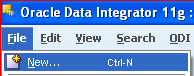
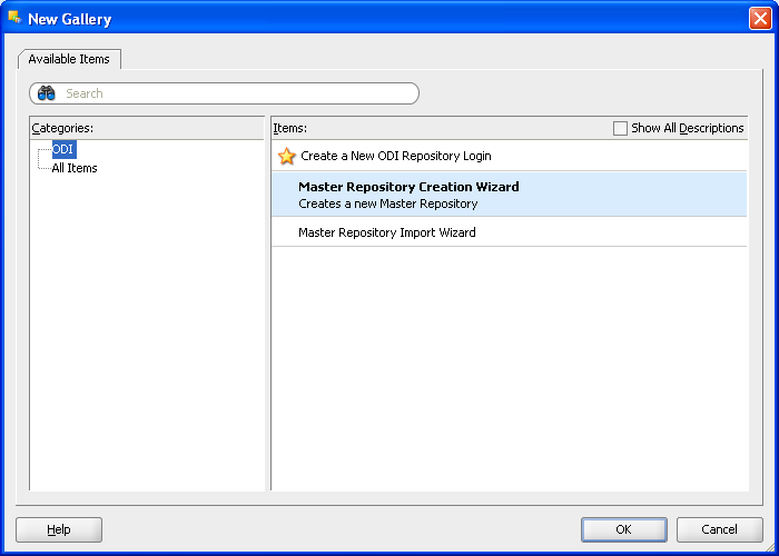
Open the New Gallery:
File > New
In the New Gallery, in the Categories tree, select ODI.
Select from the Items list the Master Repository Creation Wizard.
Click OK.
The Master Repository Creation Wizard appears.
Figure A-3 ODI Studio New Gallery Create Master Repository
In the Master Repository Creation Wizard, select the browse icon of the JDBC Driver and then select Oracle JDBC Driver. Click OK.
Edit the JDBC URL to read: jdbc:oracle:thin: @localhost:1521:orcl
Enter the User as repo and the Password as password.
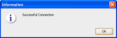
Click Test Connection and verify successful connection.
Click OK.
On the Master Repository Creation Wizard screen, Click Next.
Figure A-4 ODI Studio Master Repository Creation Wizard
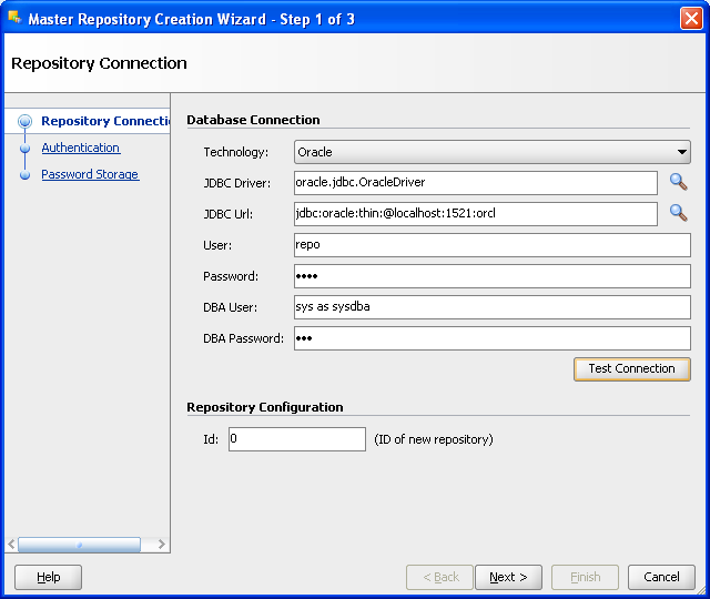
Figure A-5 ODI Studio Master Repository Successful Creation
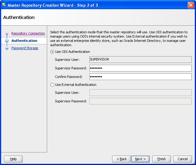
In the Authentication window, enter Supervisor Password as password.
Enter password again to confirm the password.
Click Next.
Note: ODI User names and passwords are case-sensitive.
Figure A-6 ODI Studio Master Repository Creation Password
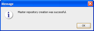
In the Password Storage window, select Internal password Storage, and then click Finish. When Master Repository is successfully created, you will see the Oracle Data Integrator Information message.
Click OK. The ODI Master repository is now created.
Figure A-7 ODI Studio Master Repository Creation Finish
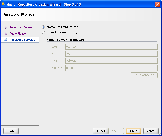
Figure A-8 ODI Studio Master Repository Creation Complete
You connect to the ODI Master repository by creating a new ODI Master Login. Open the New Gallery by choosing File > New. In the New Gallery, in the Categories tree, select ODI. From the Items list select Create a New ODI Repository Login.
Figure A-9 ODI Studio New Gallery ODI Repository Login

Configure Repository Connections with the parameters from the tables provided below. To enter the JDBC URL, click the button next to JDBC URL field and select jdbc:oracle:thin:@<host>:<port>:<sid> as shown in the screenshot, then edit the URL. Select Master Repository only button.
Click Test.
Verify successful connection and click OK.
Click OK to save the connection.
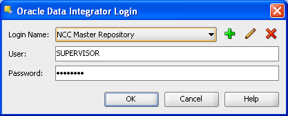
Table A-1 Oracle Data Integrator Connection
| Parameter | Value |
|---|---|
|
Login Name |
NCC Master Repository |
|
User |
SUPERVISOR |
|
Password |
password |
Table A-2 Database Connection (Master Repository)
| Parameter | Value |
|---|---|
|
User |
repo |
|
Password |
password |
|
Driver List |
Oracle JDBC Driver |
|
Driver Name |
oracle.jdbc.OracleDriver |
|
Url |
jdbc:oracle:thin:@<system_name>:<listener port>:<SID> For example: jdbc:oracle:thin:@localhost:1521:orcl |
Note: Do not copy and paste in the JDBC URL field. This may cause problems with entering a valid URL string. Instead, open the drop-down menu and select the correct driver from the list. Type the correct URL in the URL field.
Figure A-10 ODI Studio Repository Connection Information
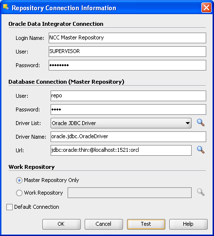
Figure A-11 ODI Studio Repository Connection Successful
Click Connect to Repository. Select the newly created repository connection Master Repository from the drop-down list. Click OK. The ODI Topology Manager starts. You are now successfully logged in to the ODI Topology Manager.
Figure A-12 ODI Studio Connect to Repository
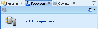
Figure A-14 Oracle Data Integrator NCC Master Repository Topology
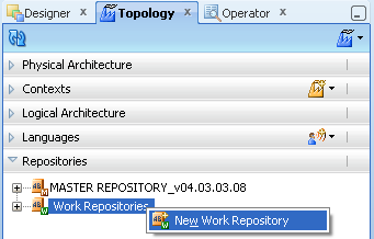
After you create the Oracle Database schema and user, use ODI Topology Navigator to create the ODI Work repository.
In ODI, click the Topology Navigator tab and then click Repositories panel. Right-click the Work Repositories node and select New Work Repository.
The Create Work Repository Wizard opens.
Figure A-15 ODI Topology Navigator New Work Repository
In the screen that follows, enter the parameters shown in Table A-3.
Click Test to verify a successful connection and click OK.
Click Next.
Table A-3 New Work Repository Parameters
| Parameter | Value |
|---|---|
|
Technology |
Oracle |
|
Driver Name |
oracle.jdbc.driver.OracleDriver |
|
JDBC Url |
jdbc:oracle:thin:@<system_name>:<listener port>:<SID> For example: jdbc:oracle:thin:@localhost:1521:orcl |
|
User |
wrep |
|
Password |
password |
Figure A-16 ODI Studio Create Work Repository Test Connection
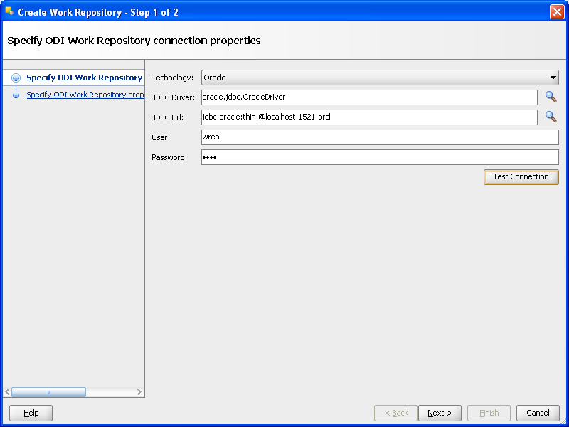
Figure A-17 ODI Repository Create Work Repository Successful Connection
In the Specify ODI Work Repository properties page, set the following values:
Set Id to: 1.
Set Name to: WORKREP_NCC.
Enter Password: password.
In the Work Repository Type list, select Development.
Click Finish.
Figure A-18 ODI Studio Create ODI Work Repository Properties
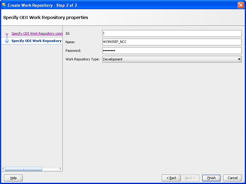
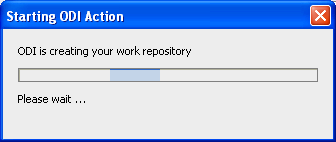
Figure A-19 ODI Studio Create ODI Work Repository Starting ODI Action
In the Create Work Repository Login window, click Yes.
Enter the Login name: NCC Work Repository.
Click OK.
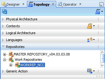
Verify that the newly created work repository is now in the work repositories tree view.
Figure A-20 ODI Studio Create ODI Work Repository Create Login
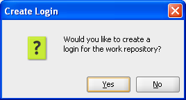
Figure A-21 ODI Studio ODI Work Repository Enter Login Name
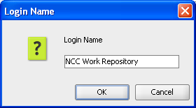
Figure A-22 ODI Studio ODI Work Repository Topology
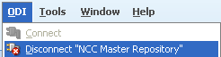
Now you disconnect from the Master repository and connect to the Work repository.
Click ODI and select Disconnect "NCC Master Repository".
Figure A-23 ODI Studio Disconnect from Master Repository
Click Connect to Repository.
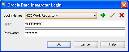
From the Login Name drop-down list, select "NCC Work Repository".
Enter Password: password.
Click OK.
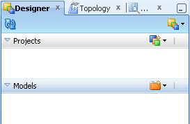
Click the Designer tab.
The ODI Designer screen appears as shown in Figure A-24.
Figure A-24 ODI Studio Connect to Repository NCC Work Repository
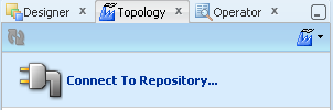
Figure A-25 ODI Studio Oracle Data Integrator Login
You have now successfully created and connected to the ODI Work repository.
If you check Designer tab no Projects and Models have existed in this work repository.
The Master Repository Import and Export procedure allows you to transfer the whole repository, Topology and Security domains included, from one repository to another.
To import a master repository in an existing master repository:
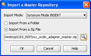
From the Topology Navigator toolbar menu select Import > Master Repository...
Select the Import Mode and the import Folder or Zip File.
Click OK.
The specified file(s) are imported into the current master repository.
Figure A-27 ODI Studio Import Master Repository
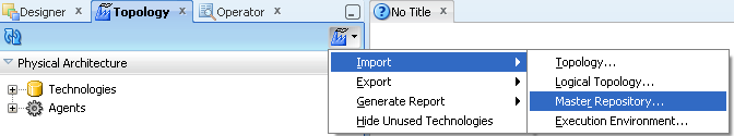
Figure A-28 ODI Studio Import Master Repository Mode and Options
Browse Master Repository from below specified location
Repository Location:
"$NCC_OCDM_HOME/odi_repository/ncc_ocdm_adapter_master.zip"
Figure A-29 ODI Studio Open and Import Master Repository
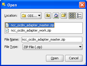
Figure A-30 ODI Studio Import Master Repository Progress
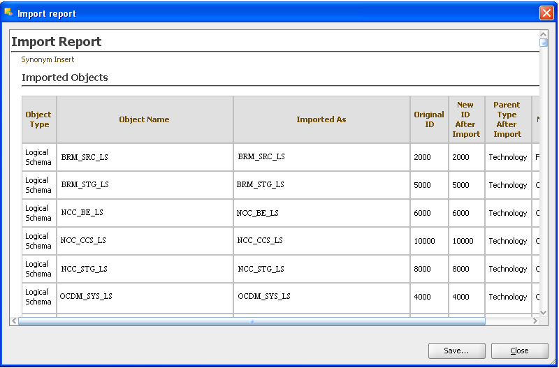
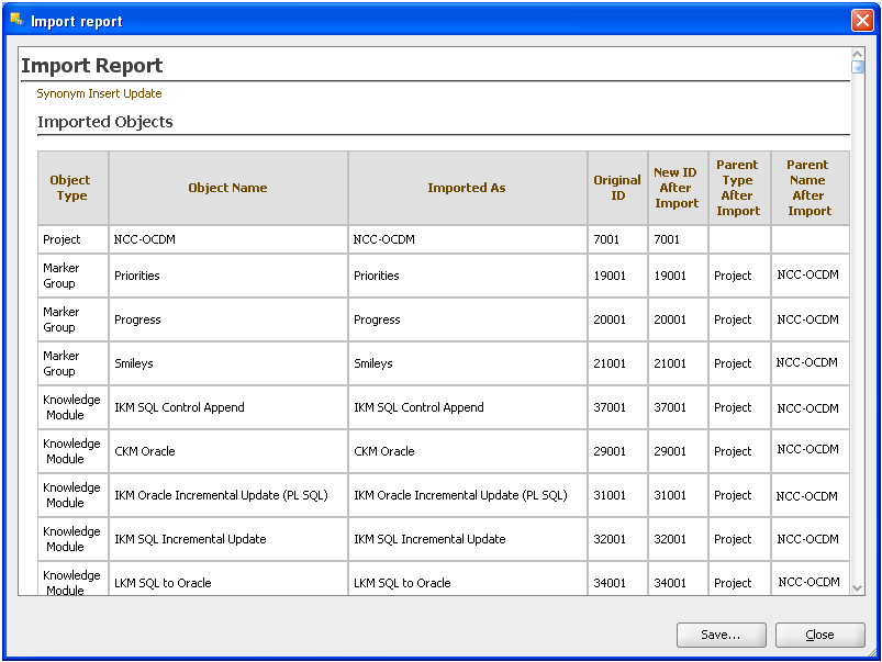
Check the Import Report and save this report by clicking Save.
Figure A-31 ODI Studio Import Master Repository Report
Importing or exporting a work repository allows you to transfer all work repository objects from one repository to another.
To import a work repository:
From the Designer Navigator toolbar menu select Import > Work Repository...
Select the Import Mode and the import Folder or Zip File.
Click OK.
The specified file(s) are imported into the work repository.
Figure A-32 ODI Studio Import Work Repository
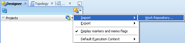
Figure A-33 ODI Studio Import Work Repository from Zip File
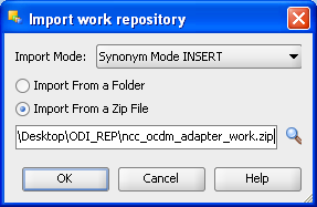
Browse Work Repository from the specified location:
$NCC_OCDM_HOME/odi_repository/ncc_ocdm_adapter_work.zip
Figure A-34 ODI Studio Open Work Repository
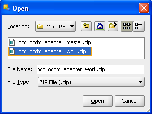
Figure A-35 ODI Studio Open and Import Work Repository Progress
Figure A-36 ODI Studio Import Work Repository Warning
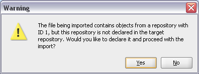
You can check the Import Report and you can save the report by clicking Save.
Figure A-37 ODI Studio Import Work Repository Report
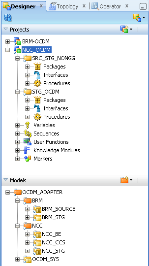
If you use the Designer tab Projects and Models you can view the projects and models that are in the work repository.
Figure A-38 ODI Studio Designer Tab Viewing Projects and Models
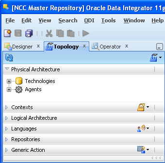
To set up the ODI Topology, do the following:
To set up the Physical Data Servers:
From the Topology Navigator Display the Physical Architecture tab.
Expand the Technologies node.
Expand the Oracle node to display the Physical Data Servers.
Figure A-39 ODI Studio Physical Data Servers
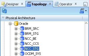
Double-click the NCC_STG node to display the Data Server: <Name> dialog.
Display the Definition tab and enter the appropriate information, as described in Table A-4.
Figure A-40 ODI Studio Data Server Definition Dialog
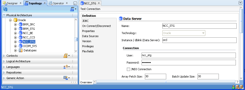
Table A-4 ODI Studio Data Server Definition Fields and Values
| Field | Description |
|---|---|
|
Name |
Do not change name of the Data Server. |
|
Technology |
Do not change the default value Oracle. |
|
Instance/dblink (Data Server) |
Specify a database instance name. Use the Oracle SID name. For example, ORCL |
|
User |
Specify <User Name>. For example, ncc_stg This is the warehouse database user name. |
|
Password |
Specify <Password>. For example, ncc_stg This is default password for the warehouse database user name. |
|
Array Fetch Size |
Specify a value suitable to your environment (Do not change the default value). |
|
Batch Update Size |
Specify a value suitable to your environment (Do not change the default value). |
Display the JDBC tab and enter the appropriate information, as described in Table A-5.
Figure A-41 ODI Studio Data Server JDBC Tab
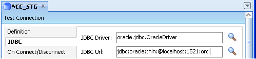
Table A-5 ODI Studio Data Server JDBC Tab Fields and Values
| Field | Description |
|---|---|
|
JDBC Driver |
Specify oracle.jdbc.driver.OracleDriver. |
|
JDBC Url |
Specify in the format jdbc:oracle:thin:@<host>:<port>:<sid>. Replace <host>, <port> and <sid> with the values for the database hosting the ODI Repositories. For example, 'jdbc:oracle:thin:@localhost:1521:orcl'. |
Click Test to display the Test Connection for: <Connection> dialog.
Figure A-42 ODI Studio Data Server Test Connection

Click the Save icon to save the details.
Note:
Follow the same steps (1-8) to configure NCC_BE, NCC_CCS and OCDM_SYS Physical Data Servers.To set up the Physical Schema for a Data Server:
From the Topology Navigator Display the Physical Architecture tab.
Expand the Technologies node.
Expand the Oracle node to display the Physical Data Servers.
Expand the Data Server node.
Figure A-43 ODI Studio Physical Architecture Data Server Node
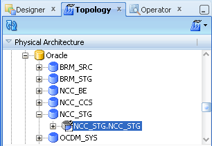
Double-click NCC_STG.NCC_STG to display the Physical Schema: <Name> dialog.
Display the Definition tab and enter the appropriate information, as described in Table A-6.
Figure A-44 ODI Studio Physical Schema Definition Tab
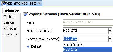
Table A-6 ODI Studio Physical Schema Definition Tab Properties and Values
| Field | Description |
|---|---|
|
Schema (Schema) |
Make sure that <Physical Schema> is selected from the drop down list.(For example: NCC_STG) |
|
Schema (Work Schema) |
Make sure that <Physical Schema> is selected from the drop down list.(For example: NCC_STG) |
Note: Do not change the other field values.
Click to save the details.
Note: Follow the same steps (1-7) to configure NCC_BE, NCC_CCS and OCDM_SYS Physical Schemas.
To set up the Logical Data Servers:
From the Topology Navigator Display the Logical Architecture tab.
Expand the Technologies node.
Expand the Oracle node to display the Logical Data Servers.
Figure A-45 ODI Studio Logical Architecture for Logical Data Server
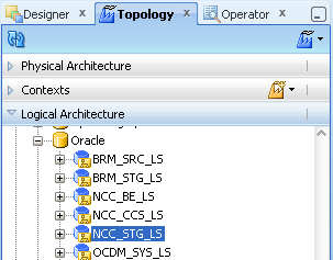
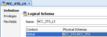
Double-click the NCC_STG_LS node to display the Logical Data Server: <Name> dialog.
Display the Definition tab.
Edit the NCC_STG_LS Logical Data Server and ensure that for the appropriate Context (for example, Global, Development...), the value in the Physical Schemas column is set to NCC_STG.NCC_STG'(Physical Schema created in Physical Data Server).
Figure A-46 ODI Studio Logical Data Server Definition Tab for Logical Schema
Click the Save icon to save the details.
Note: Follow the same steps (1-7) to configure NCC_BE_LS, NCC_CCS_LS and OCDM_SYS_LS Logical Data Server.
To set up Oracle GoldenGate for Oracle Communications Data Model, you perform the following steps:
To install Oracle GoldenGate, do the following:
Change directory to the database installation path (For example: /u02/app/oracle/product).
Figure A-47 Changing Directory to the Oracle GoldenGate Installation Path
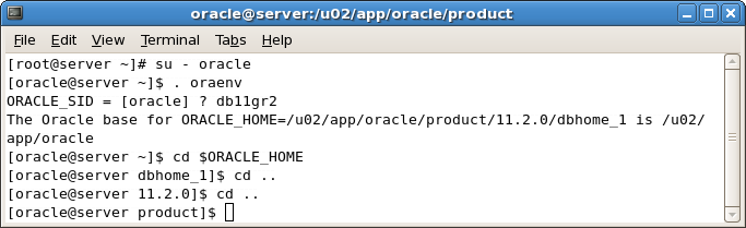
Create a directory named (gg) for installing Oracle GoldenGate under the product folder:
[oracle@server product]$ mkdir /u02/app/oracle/product/gg
Or manually create the folder (gg) by going directly in the product folder:
[oracle@server product]$ export GGATE= /u02/app/oracle/product/gg
[oracle@server product]$ cd $GGATE
[oracle@server gg]$
Copy the downloaded Oracle GoldenGate (for example: V22228-01.zip) into gg folder (for information on downloading Oracle GoldenGate, see "Oracle GoldenGate").
Unzip the software in the folder using following command:
[oracle@server gg]$ unzip V22228-01.zip
After you unzip the file, use the .tar extension file to extract Oracle GoldenGate.
Tar the Oracle GoldenGate .tar file using the following command:
[oracle@server gg] tar -xf <filename>.tar
Now export the path to GG libraries to LD_LIBRARY_PATH using the command:
export LD_LIBRARY_PATH=$ORACLE_HOME/lib:/u02/app/oracle/product/gg
Now start the GG command line utility (ggsci):
[oracle@server gg]$. /ggsci
This command connects you to the Oracle GoldenGate server.
For example:
Oracle GoldenGate Command Interpreter for Oracle Version 11.1.1.0.0 Build 078 Linux, x86, 32bit (optimized), Oracle 11 on Jul 28 2010 13:22:25 Copyright (C) 1995, 2010, Oracle and/or its affiliates. All rights reserved.

GGSCI (server.oracle.com) 1>
Create the necessary working directories for gg:
GGSCI (server.oracle.com) 1>create subdirs
GGSCI (server.oracle.com) 2>exit
[oracle@server gg]$ mkdir $GGATE/diroby
[oracle@server gg]$ mkdir $GGATE/discard
After these steps Oracle GoldenGate is installed.
After Oracle GoldenGate is installed you prepare and configure the source and target database for Oracle GoldenGate Replication.
To set up the Oracle GoldenGate Schema:
Switch the database server to archive log mode.
Note:
Setting the database server to archivelog mode is recommended on a production system. This mode is not required for testing or for use on a development system.Connect to sqlplus from oracle user:
[oracle@server dbhome_1]$ sqlplus / as sysdba
SQL>shutdown immediate
SQL>startup mount
SQL>alter database archivelog;
SQL>alter database open;
Enable minimal supplemental logging:
SQL>alter database add supplemental log data;
Figure A-48 Commands to Set Database Options for Oracle GoldenGate Configuration

Switch log to start supplemental logging:
SQL> ALTER SYSTEM SWITCH LOGFILE;
SQL> ALTER SYSTEM SWITCH LOGFILE;
Verify supplemental logging is enabled (with the following command showing a result: 'YES').
SQL> SELECT SUPPLEMENTAL_LOG_DATA_MIN FROM V$DATABASE;
Prepare the database to support database replication. Turn off recyclebin for the database:
SQL>alter system set recyclebin=off scope=spfile;
Create the schema for ddl replication:
SQL>create user ggate identified by qwerty default tablespace users temporary tablespace temp;
Grant necessary privileges to the new user:
SQL> grant connect,resource to ggate;
SQL> grant select any dictionary, select any table to ggate;
SQL> grant create table to ggate;
SQL> grant flashback any table to ggate;
SQL> grant execute on dbms_flashback to ggate;
SQL> grant execute on utl_file to ggate;
SQL> GRANT SELECT ANY TABLE, INSERT ANY TABLE, UPDATE ANY TABLE, DELETE ANY
TABLE TO GGATE;
SQL> Grant alter any table to ggate;
Exit SQL:
SQL>exit
Go to the following path and issue the following commands:
[oracle@server product]$ export GGATE= /u02/app/oracle/product/gg
[oracle@server product]$ cd $GGATE
These commands change the prompt to:
[oracle@server gg]$
Start sqlplus:
[oracle@server gg]$sqlplus '\ as sysdba'
Now run the supplied scripts and verify the creation of the necessary objects to support ddl replication:
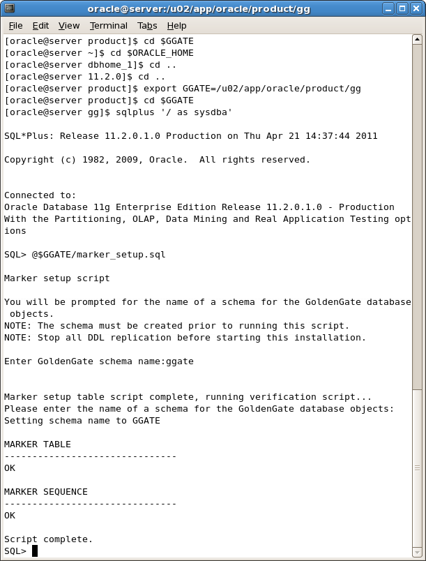
Run the script:
SQL> @$GGATE/marker_setup.sql
With this command you will be prompted for the name of the schema:
Enter the schema as: ggate
Figure A-49 shows the screenshot for these steps.
Figure A-49 Configuring Oracle GoldenGate
Execute the script:
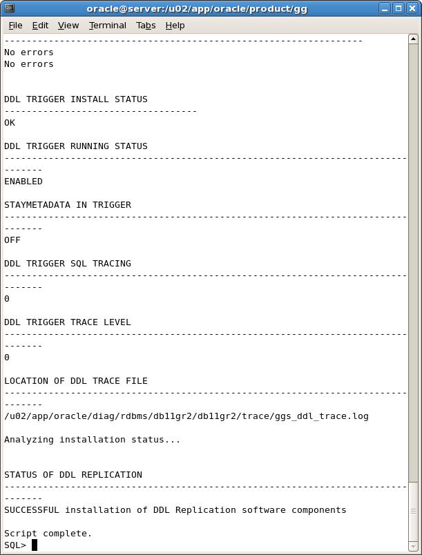
SQL> @$GGATE/ddl_setup.sql
Figure A-50 Oracle GoldenGate Configuration Running ddl_setup Script
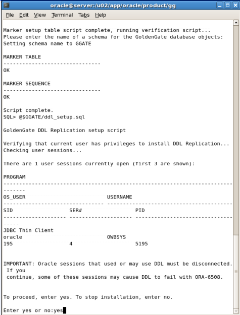
After entering the value: Yes you should see the values shown in Figure A-51.
Figure A-51 Oracle GoldenGate Configuration Values from ddl_setup Script
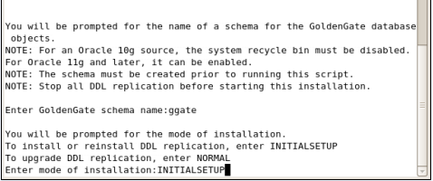
After entering INITIALSETUP you see the result as shown in Figure A-52.
Figure A-52 Oracle GoldenGate Configuration with Script Complete ddl_setup Screen
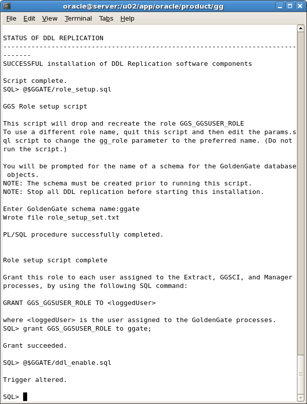
Enter the command to run the role_setup.sql script:
SQL> @$GGATE/role_setup.sql
Enter the command to grant access to the GGS_GGUSER_ROLE:
SQL> grant GGS_GGSUSER_ROLE to ggate;
Enter the command to run the ddl_enable.sql script:
SQL> @$GGATE/ddl_enable.sql
Follow the prompts as shown in Figure A-53.
Figure A-53 Oracle GoldenGate Configuration for Scripts: role_setup.sql,
Connect to ggate user and check that the following 13 tables were created:
GGS_BF_CACHE
GGS_DDL_COLUMNS
GGS_DDL_HIST
GGS_DDL_HIST_ALT
GGS_DDL_LOG_GROUPS
GGS_DDL_OBJECTS
GGS_DDL_PARTITIONS
GGS_DDL_PRIMARY_KEYS
GGS_MARKER
GGS_SETUP
GGS_STICK
GGS_TEMP_COLS
GGS_TEMP_UK
Note:
Follow the same steps in "Installing Oracle GoldenGate" and "Configuring Oracle GoldenGate" to install and configure Oracle GoldenGate in source systems (ncc_ccs and ncc_be) and the staging server (ncc_stg).Table A-7 provides a summary of Oracle GoldenGate process commands. Note: Run these commands from GGSCI.
Table A-7 Oracle GoldenGate Process Commands Summary
| Process Area | Commands |
|---|---|
|
To Start All Services |
Manager: Extract: Replicate: Extract & Replicat: |
|
To Stop All Services |
Manager: Extract: Replicate: Extract & Replicat: |
|
To Check Services Status |
All Services: Manager: Extract: Replicate: |
|
To View Report |
Extract: Replicate: |
The goals of this method are to:
Configure and add the Extract process that will capture changes
Add the local trail that will store these changes
Configure and add a data pump Extract to read the local trail and create a remote trail on the target
Add the remote trail
Start the two Extract processes
Configure the Primary Extract and Data Pump
Add the Extract group and data pump Extract group
On the src_ccs Source System:
Execute the following command on the CCS <source> system to define an Extract group named ext1 and to define a data pump Extract named dpump to pull data from the local GoldenGate trail and route these changes to GoldenGate on the target:
[oracle@server gg]$ $GGATE/./ggsci paramfile $GGATE/diroby/ncc_ogg_src_cdc_cmd_101_sms.oby
On the be_ccs Source System:
Execute the following command on the BE <source> system to define an Extract group named ext1 and to define a data pump Extract named dpump to pull data from the local GoldenGate trail and route these changes to GoldenGate on the target:
[oracle@server gg]$ $GGATE/./ggsci paramfile $GGATE/diroby/ ncc_ogg_src_cdc_cmd_102_vws.oby
Note: In a non Oracle RAC environment, the THREADS parameter can be omitted or the THREADS <instances> can be set to 1.
Add the Replicat groupExecute the following command on the <staging> system to add delivery groups named rep1 and rep2:
[oracle@server gg]$ $GGATE/./ggsci paramfile $GGATE/diroby/ ncc_ogg_stg_cdc_cmd.oby
Note: Refer to your Extract set up for the correct two-character <trail id>.
Start the primary Extract process and data pump Extract process:
Execute the following command on the <source> systems:
On the src_ccs Source System:
[oracle@server gg]$ $GGATE/./ggsci paramfile $GGATE/diroby/ncc_ogg_src_cdc_start_cmd_101.oby
On the be_ccs Source System:
[oracle@server gg]$ $GGATE/./ggsci paramfile $GGATE/diroby/ncc_ogg_src_cdc_start_cmd_102.oby
Execute the following command on the <staging> system.
[oracle@server gg]$ $GGATE/./ggsci paramfile $GGATE/diroby/ncc_ogg_stg_cdc_start_cmd.oby
|
Copyright © 2010, 2012, Oracle and/or its affiliates. All rights reserved. Legal Notices |
|